
Flash trimming of forged parts
A forged part comes out of the press with its flash. Our trimming line takes it off right away, before the part goes anywhere else, and keeps a fast pace part after part. Turnkey, press included.
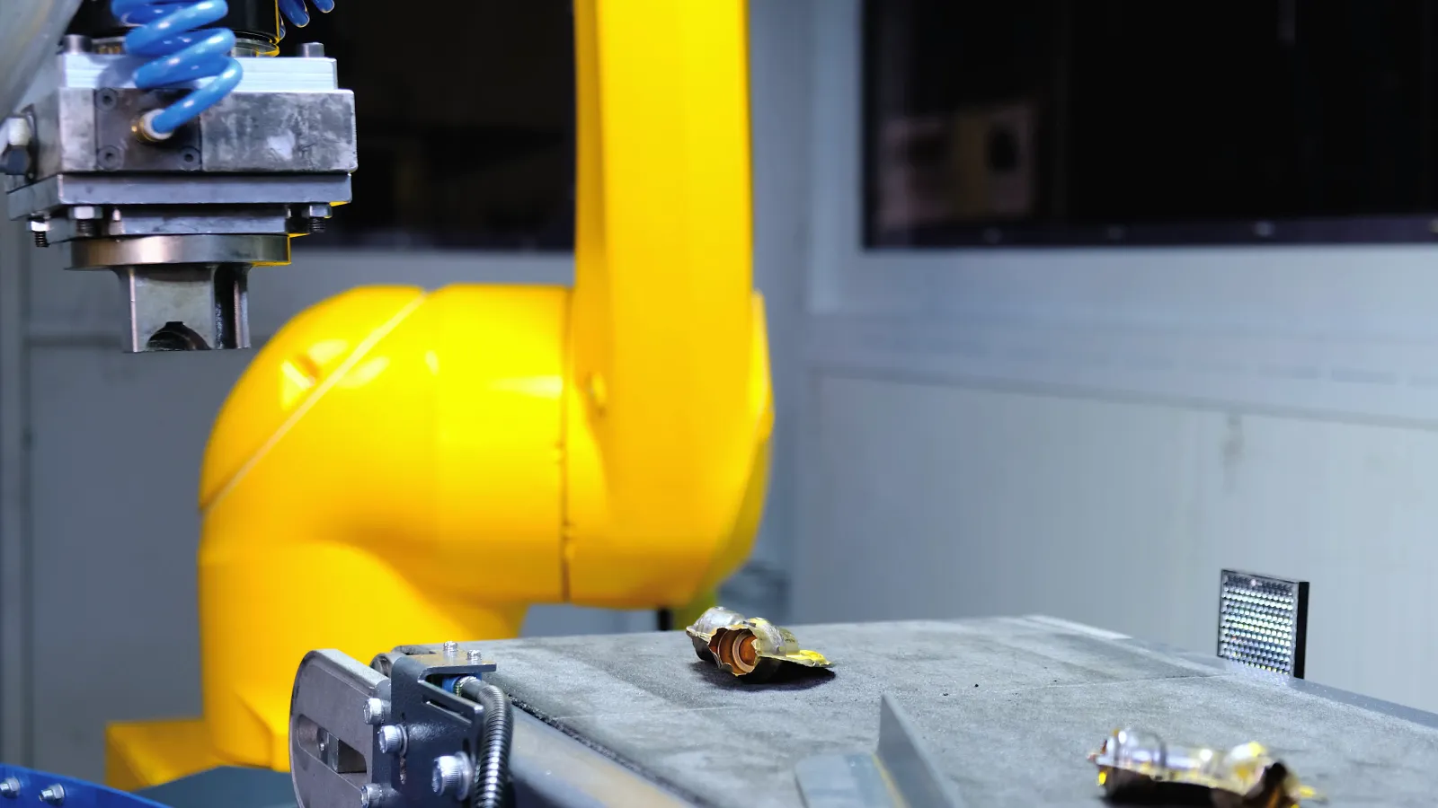
01Picked off the conveyor 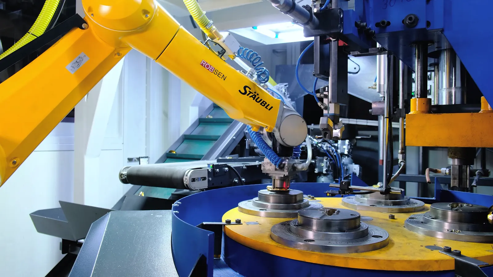
02Into the die 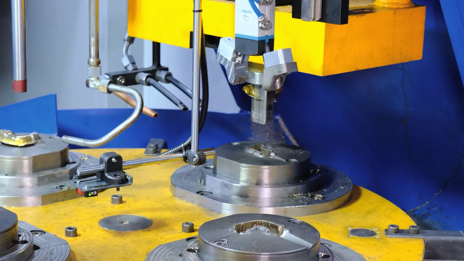
03Seated and trimmed 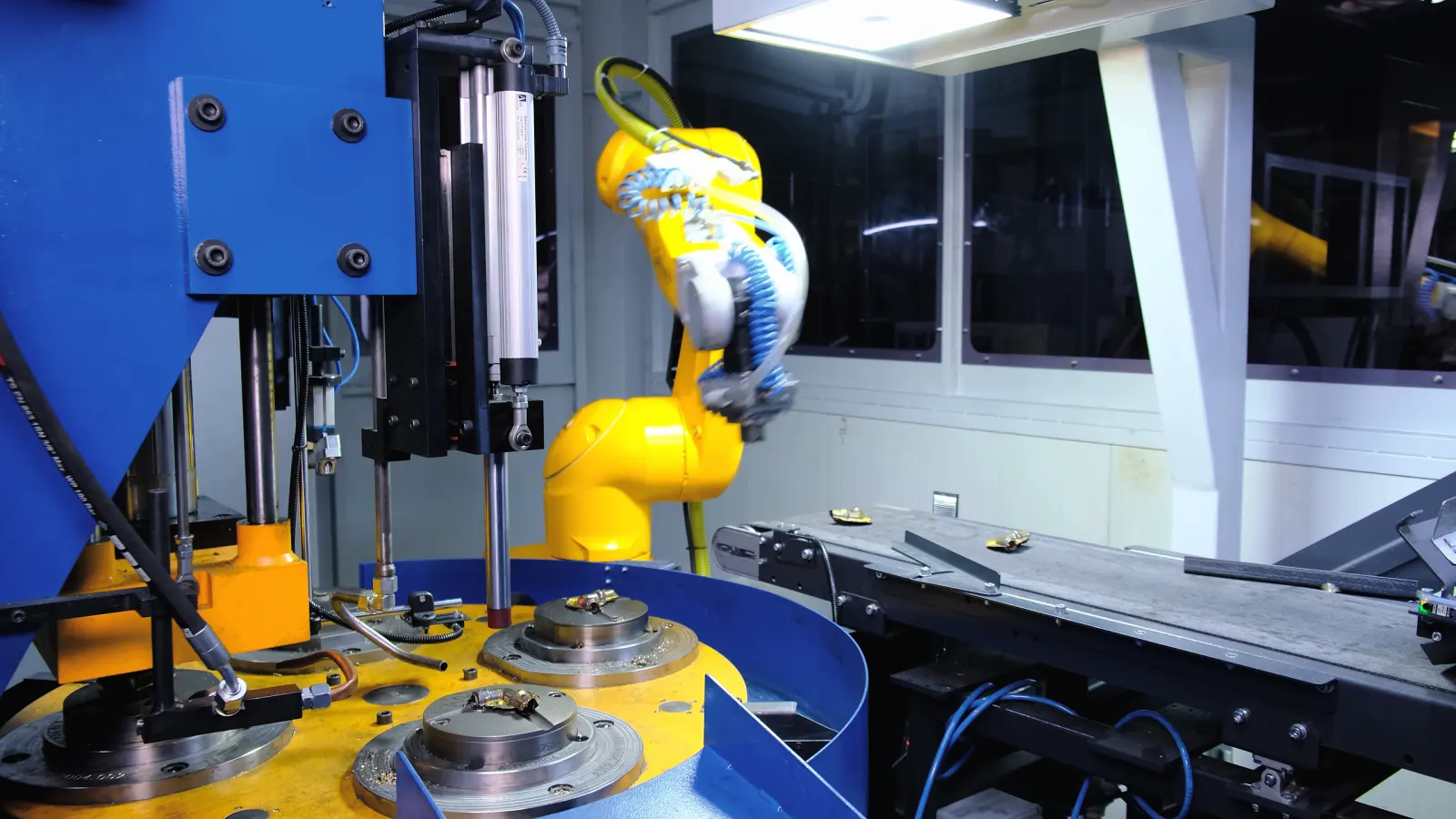
04Back for the next
Why take the flash off first
Trimming right after forging pays off in every step that follows.
- 01
Shorter machining, longer tool life
The machining center no longer cuts flash. Machining time goes down and the tools last longer.
- 02
No sharp edges in anyone's hands
The sharp flash is gone from the start, so the operators after the press never handle it.
- 03
Parts a robot can hold
Every trimmed part has the same shape. When the flash stays on, each part's flash is different, a secure grip gets hard and every robot operation after it gets harder.
- 04
Clean scrap, back into production
The flash comes off before it ever touches coolant or cutting oil, so it goes straight back to be melted. Left on until machining, it would first have to be filtered out of the oil.
From the bin to the bin
The drawing shows the line at work, opened out from left to right so every step can be seen.
The drawing runs slower than the real line.
- The operator sets a bin of forged parts, up to 1.5 tonnes, on the bin tipper.
- The tipper doses the parts onto a conveyor that carries them into the vibratory bowl; the bowl sends them out one by one, spaced apart.
- A camera running IROVISION, our own vision software, finds each part and the robot picks it up with a vacuum gripper. A part the camera cannot read is turned over for a second camera.
- The robot lays the part in the die on the rotary table. A seating press sets it, the trim press cuts the flash.
- The trimmed part drops into its bin, the flash is blown off into another. Each bin has its own door.
Fast cycles. At cycle times like these, feeding decides the output, so the line is fed in bulk: the operator only brings the next bin.
Follow a part through the line
The same line as a render of a cell we designed: every module the part passes, in the order it passes them.
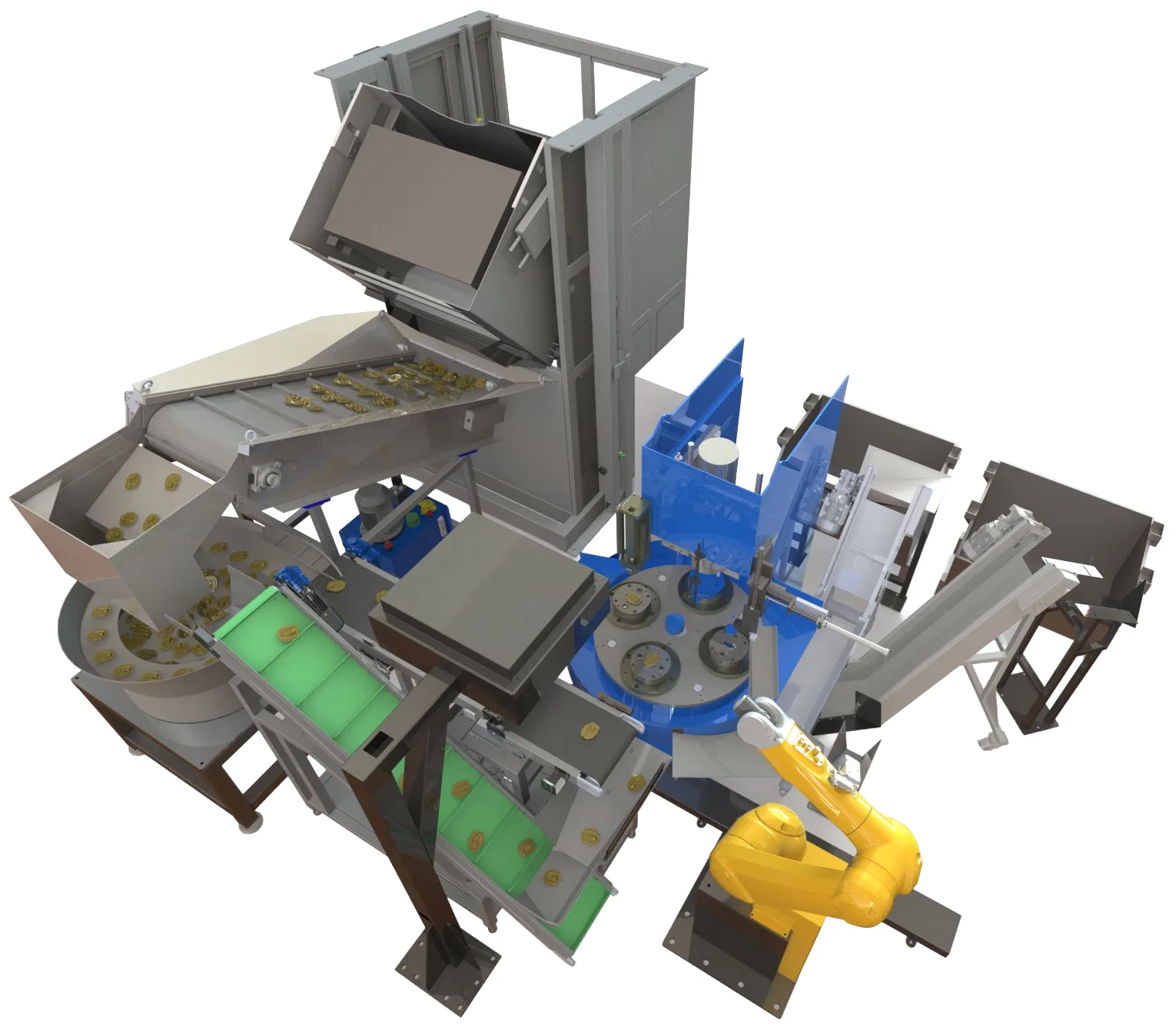
- 1
Bin tipper
The operator brings a bin of forged parts, up to 1.5 tonnes. The tipper doses them out a few at a time.
- 2
Dosing conveyor
Carries the parts on into the vibratory bowl.
- 3
Vibratory bowl
Separates the parts and sends them out one by one, spaced apart.
- 4
Camera
Over the feed conveyor, IROVISION finds each part and tells the robot where and how it lies.
- 5
Robot
Picks the part with a vacuum gripper and lays it in a die on the rotary table.
- 6
Rotary table and presses
The part is seated, trimmed and unloaded at four stations, 90° apart.
- 7
Two bins
Trimmed parts in one, flash in the other, each behind its own door.
- 8
Return conveyor
A part the cameras cannot read goes back to the bowl for another pass.
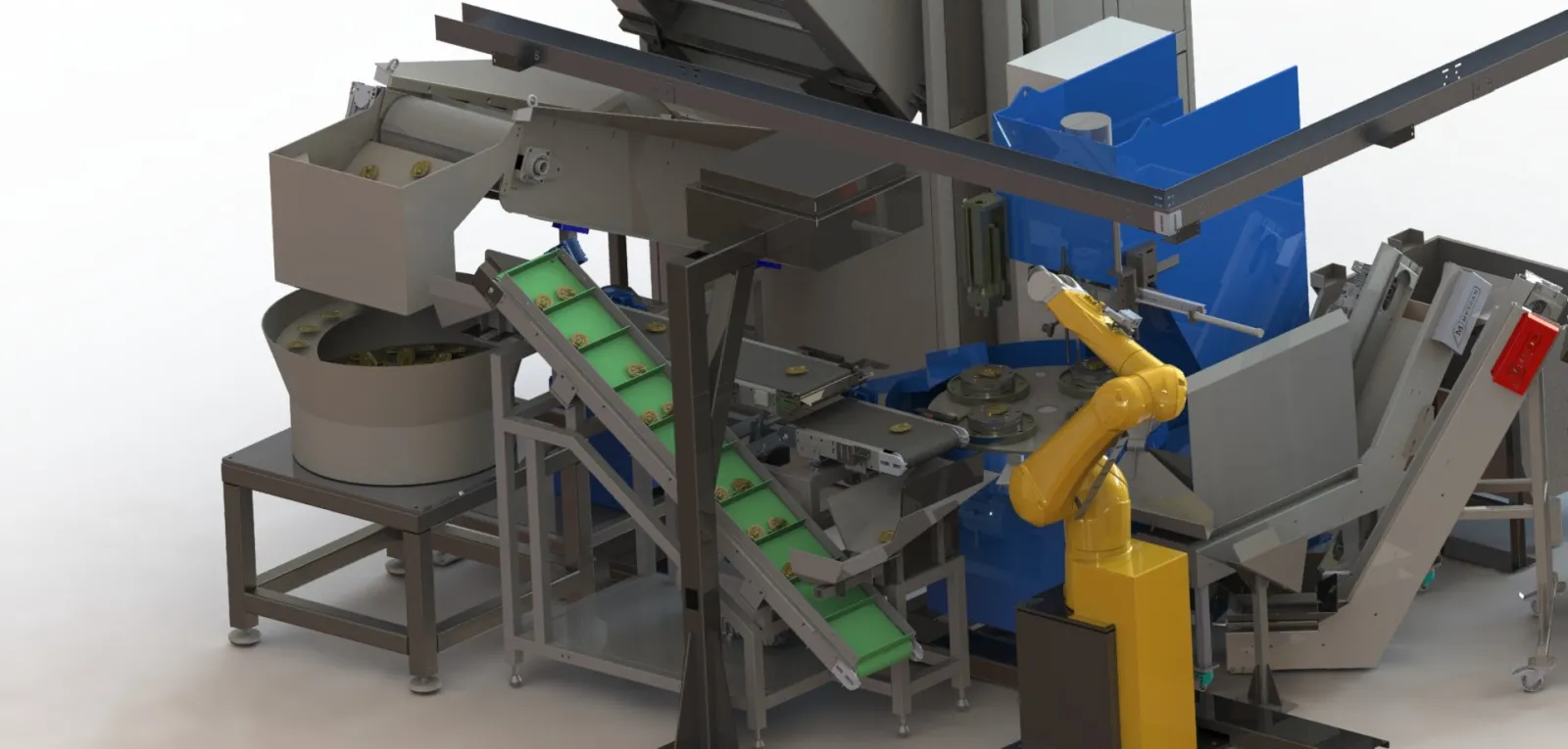
Feeding at high capacity
A line that trims parts this fast needs a lot of parts in front of it.
- 01
A bin tipper
The operator brings a bin of up to 1.5 tonnes straight from the forging press; the tipper empties it into the hopper.
- 02
Dosed, then singled out
A dosing conveyor and the vibratory bowl take the heap apart, so the parts reach the camera one at a time, spaced and steady. No fixtures and no manual sorting.
- 03
A recipe for each part
Hundreds of part types run on the same line, each with its own vision and tooling settings.
When the camera cannot read a part
- Camera 1
Finds the part. The robot picks it.
- Not read
A part upside down, a chip on the belt, an unclear outline: a flip unit turns the part over.
- Camera 2
Looks again. The robot picks it.
- Still not read
The part rolls off onto the return conveyor and goes back to the bowl for another pass.
Four stations on one table
The rotary table turns 90° at a time. Every die passes four stations before it comes back to the robot.
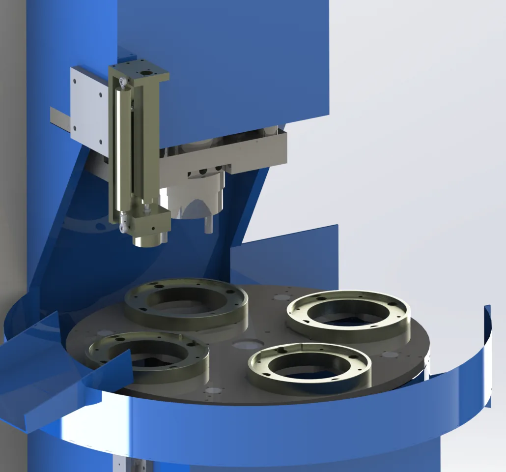
- Loading. The robot lays the part in the die.
- Seating. A pneumatic press pushes the part down so it sits right in the die.
- Trimming. The trim press cuts the flash off. The part drops through the die; the flash stays on it.
- Unloading and cleaning. A strong blast of air clears the flash from the die. A part that does not drop by itself is lifted out by a pick-off unit, and a brush cleans the die.
Turnkey, press included
We build the whole line, the hydraulic trim press included, and install it at your plant. From you we need three things:
- The cell area, cleared
- Information about your part and your press
- Sample parts
That is all. The rest is our work.
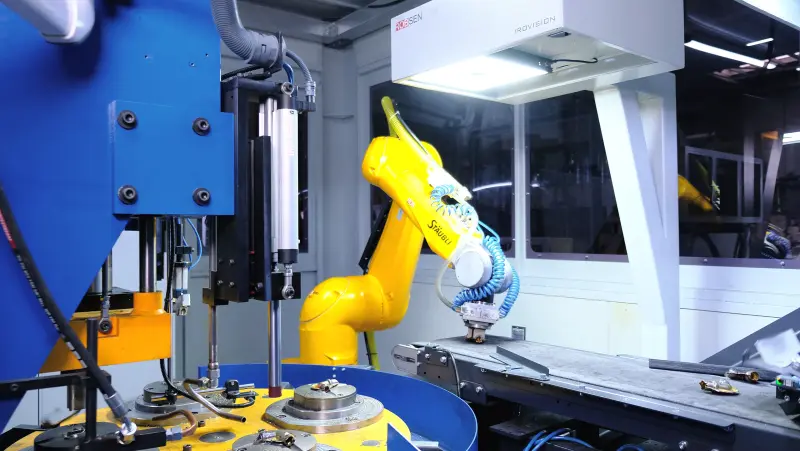
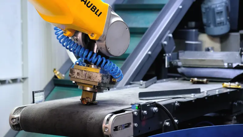
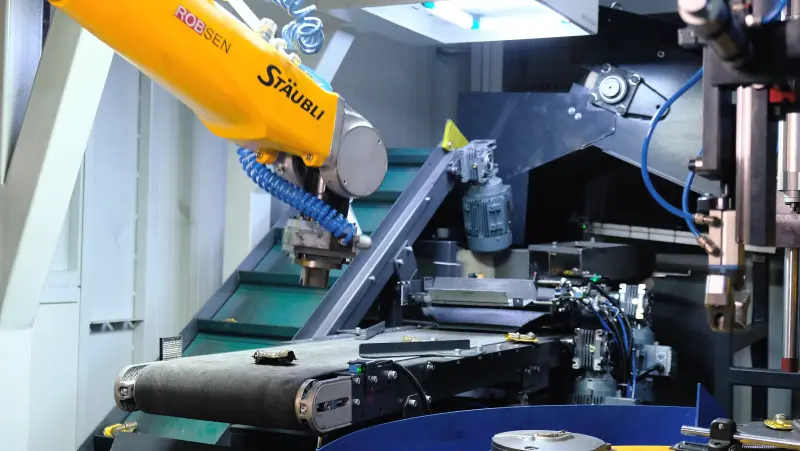
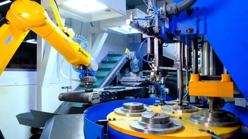
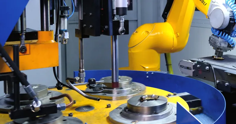
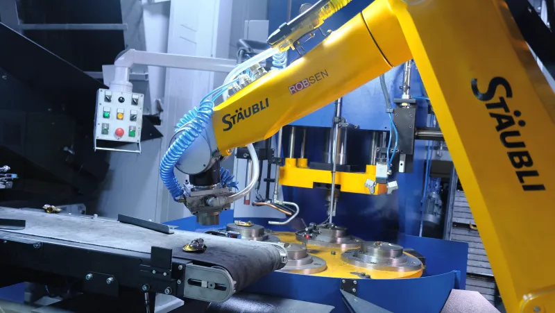
The line at work
Trimming lines we have built, running in production.


The line in brief
- Application
- Flash trimming of forged parts
- Solution
- Material Handling
- Cycle time
- Fast, set by your part and confirmed with your samples
- Feeding
- Bin tipper, bins up to 1.5 t
- Trim press
- Hydraulic, about 30 t, sized to your part
- Rotary table
- 4 stations, 90° a step
- Vision
- IROVISION, two cameras and a flip unit
- Part types
- Hundreds, a recipe for each
- Bins
- 845 × 800 × 590 mm, a door for each
- Enclosure
- Closed safety cabin, CE certified
- In the line
- Bin tipper, dosing conveyor, vibratory bowl, feed conveyor, two IROVISION cameras and a flip unit, return conveyor, robot with a vacuum gripper, rotary table with four stations, seating press, hydraulic trim press
- Delivery
- Turnkey, the press included, installed at your plant
Questions we are asked
What cycle time can the line reach?
A fast one: at the cycles this line runs, feeding rather than the press decides the output, which is why it is fed in bulk from a bin.
The exact figure depends on your part: its size, how much flash it carries, and how often it arrives the wrong way up, since those parts take the second camera or another pass through the bowl. Send us your part and samples, and we will tell you the cycle time for it.
What happens to a part that lies the wrong way up?
If the first camera cannot read it, a flip unit turns it over for a second camera. If that camera cannot read it either, the part rolls onto the return conveyor and goes back to the bowl for another pass. The robot only picks a part a camera has located.
Where does the flash go?
At the unloading station a strong blast of air clears the flash from the die into its own bin, behind its own door. A part that does not drop by itself is lifted out by a pick-off unit, and a brush cleans the die before it comes back round to the robot.
The flash comes off clean and dry, before any coolant or cutting oil reaches it, so it goes straight back to be melted.
How do we change over to another part?
Every part has a recipe: its vision model and its tooling settings. Select the recipe on the screen and fit the part's trim die, and the line runs the new part. That is how one line handles hundreds of part types.
Is the press included, and what about our trim tools?
Yes. The hydraulic trim press is part of the line we build and install. Send us drawings of the trim tools you use today along with your sample parts, and we will tell you what the line needs.
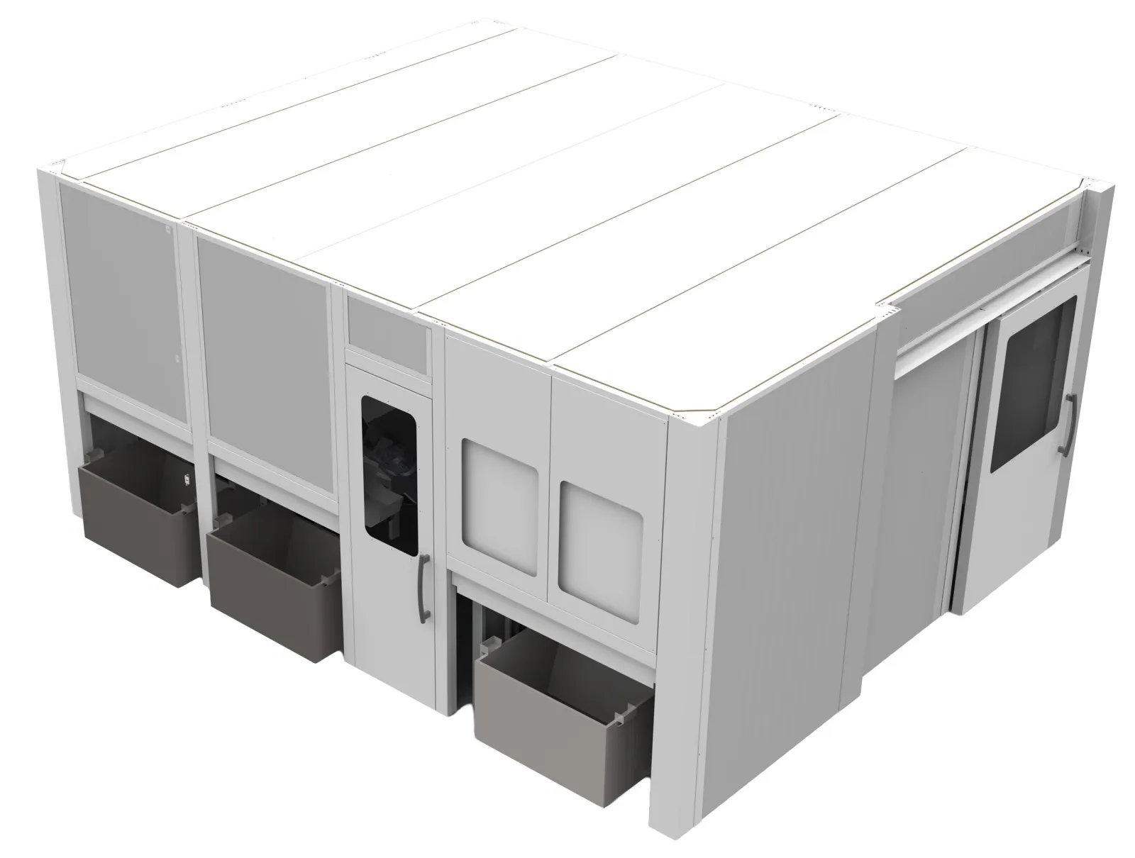
How is the line guarded?
The line runs inside a closed safety cabin. The operator works only at its three doors: one for the bin of forged parts, one for the trimmed parts and one for the flash. The line comes with its CE certification.
Why not forge without flash?
Flashless forging needs presses and dies made for it, and not every part can be forged that way. Where the dies make flash, the line takes it off right after forging, before it costs anything further down the line.
Send us your part
Every trimming line starts with the part: its flash, its die and its cycle. Tell us about your part and your press, send us samples, and we will set up the right project with you.
Talk to an engineer