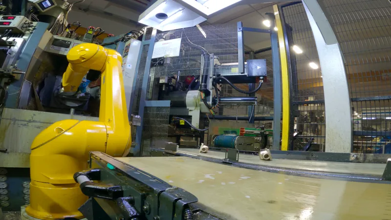
A transfer machine wants a new part every few seconds, all shift long. We fit the cell to the machine: a compact one with the robot mounted on the machine itself, a high-capacity one fed a whole bin at a time, and special cells where a machine needs its own solution.
A transfer machine works on several parts at once, one at each station. Every time it indexes, a finished part comes out and the machine asks for a new one. A part may spend minutes inside, yet the feeding has only seconds.
Real time
Real time at KAS Group: one part every 4.22 s.
01
One part at a time
Each part is taken from the batch on its own, and round parts are kept from rolling.
02
Found, not fixtured
A camera finds where each part lies and how it is turned. No tray or fixture holds it in place.
03
Held securely
The gripper copes with flash and with the small differences between forged parts.
04
Loaded right, every time
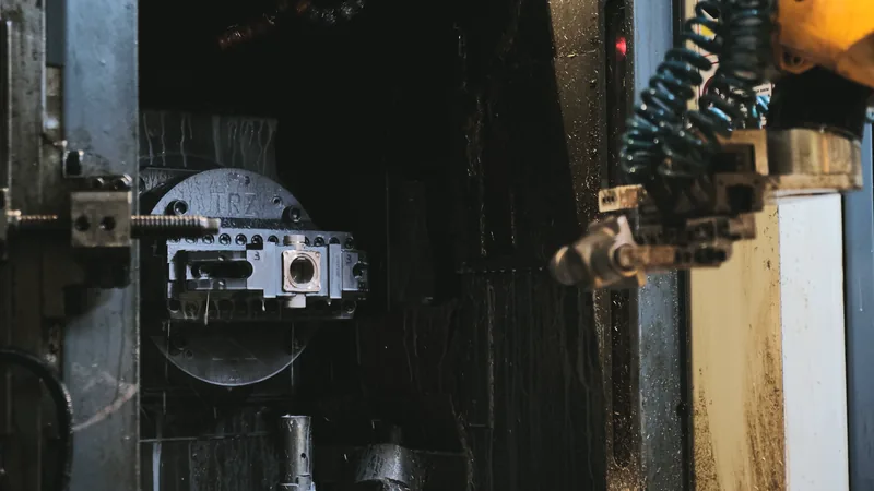
Into the jaws at the right angle, and out of the machine before it starts its cycle.
Transfer machines are usually fed by vibratory bowls, with tooling made for one part. That suits one part in long runs. It struggles when parts change often, or when forged parts carry flash that catches in the feed channels. A robot guided by a camera has neither problem.
Two cells for two kinds of production
Both are built on our own platform and guided by IROVISION, our own vision software. What differs is how the parts reach the robot.
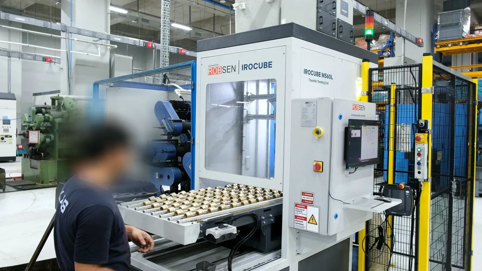
IROCUBE MS60L at a KTM transfer machineOn the machine
IROCUBE MS60L
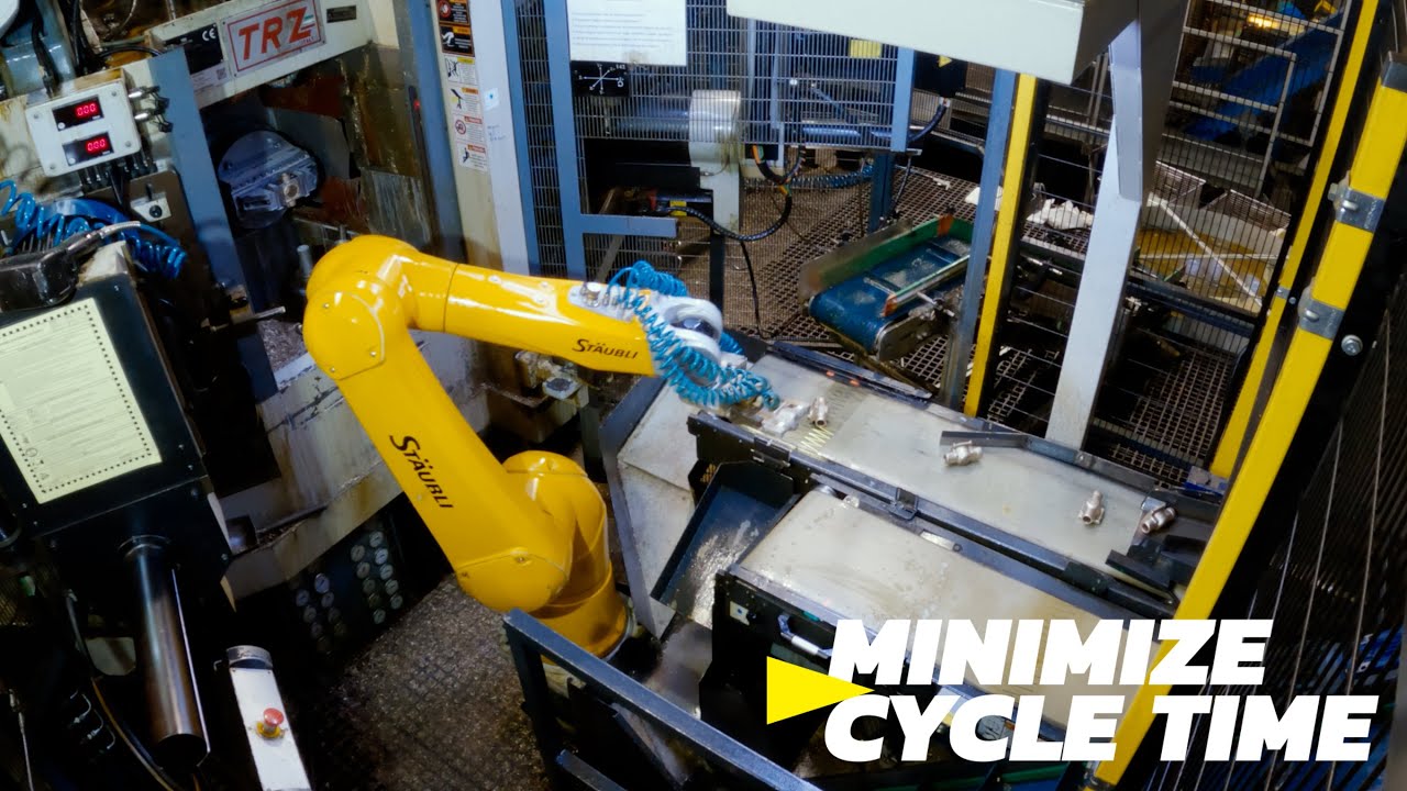
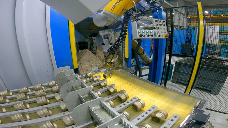
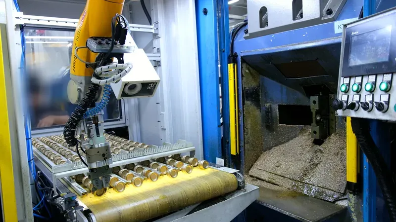
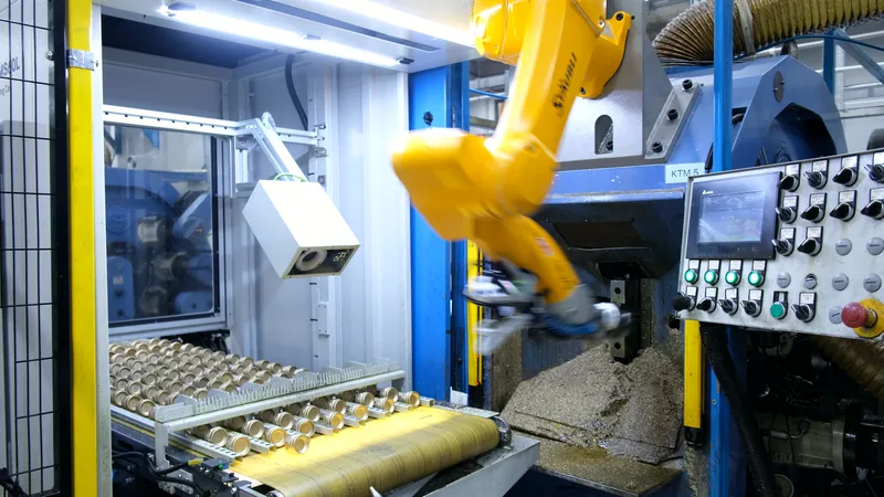
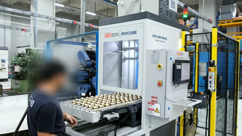
The robot is mounted on the machine itself, right above the jaws. The operator feeds a backlit conveyor in front of it.
IROVISION finds the part, so no part needs a fixture. Each part has a recipe, and a changeover means choosing it on the screen. Robot, conveyors, camera and control cabinet are built and tested at our plant before they ship.
Why the robot sits on the machine
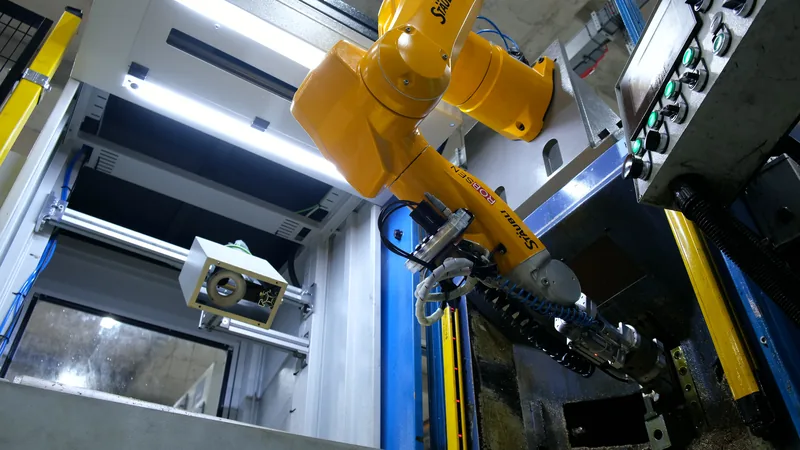
At cycles this short, every move the robot makes costs time. So we mount it on the machine, as close to the jaws as it can be.
01
The shortest path
From the conveyor to the jaws and back, with nothing in the way. That is what makes the short cycle possible.
02
The machine front stays free
A robot standing on the floor this close to the machine would block the operator’s work area. Mounted above it, the robot takes no floor space at all.
03
Moved aside for service
When the operator needs to work on the machine, they take the teach pendant and move the robot to its saved maintenance position. The machine is open for setup and maintenance.
04
A compact robot is enough
From above, a compact robot reaches both the conveyor and the jaws. No long-reach robot is needed.
Light curtains on the machine make sure the robot is out before the machine starts its cycle.
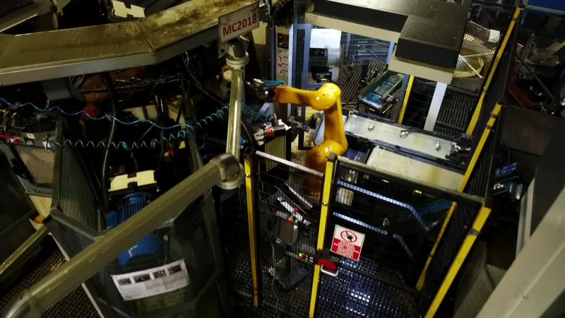
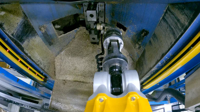
From below: the robot hangs above the machine.
From the conveyor to the jaws
How the IROCUBE MS60L feeds a transfer machine at KAS Group. Hover over a step to watch it.
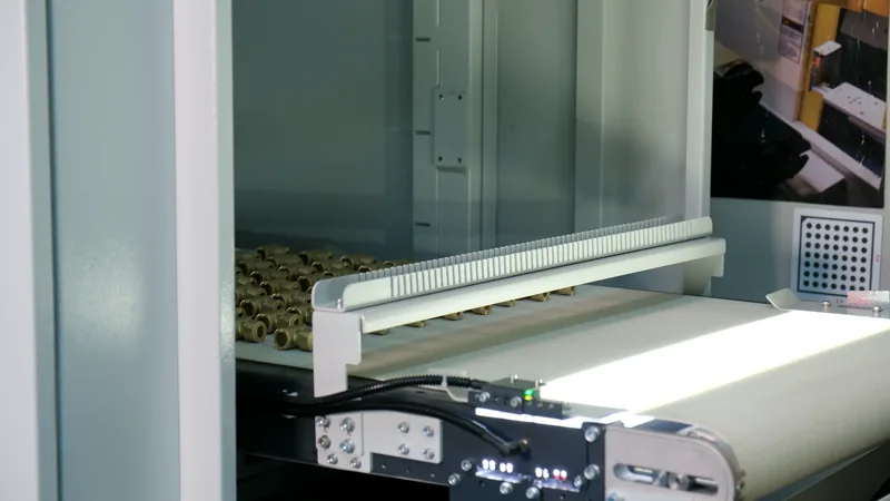
01Fed to the conveyorThe operator feeds raw parts to the conveyor. No exact placement is needed: separators keep round parts from rolling.
At our plant · 2×
02Brought forwardThe conveyor carries the batch forward and stops when the parts reach the sensor.
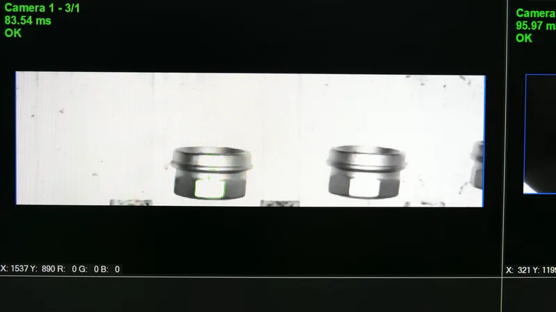
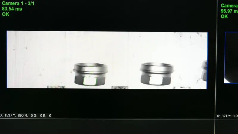
03LocatedThe first camera, on a slider, scans the backlit conveyor. IROVISION finds every part and how it lies, in about 83 ms an image.
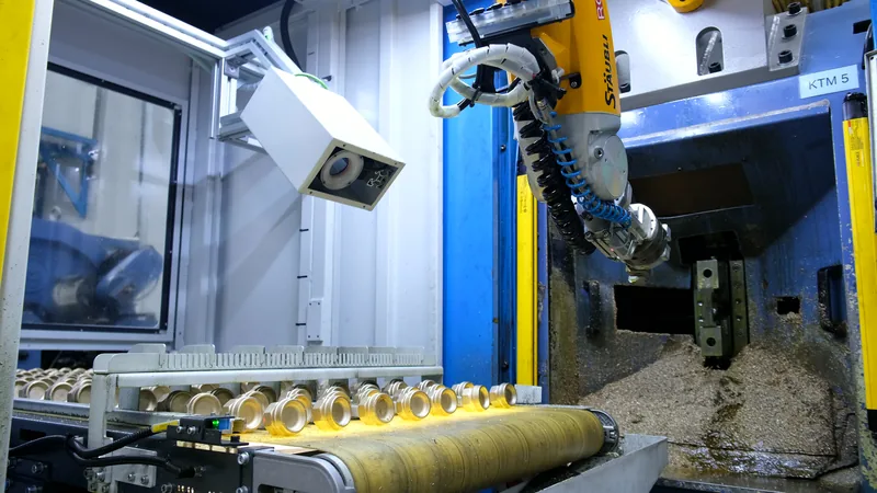
04PickedThe robot picks the parts one by one. When the batch is done, the next one comes forward.
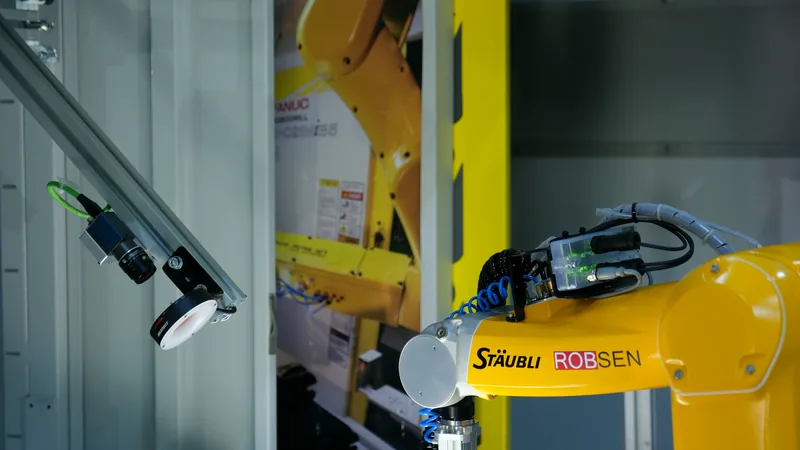
At our plant
05Angle checkedThe robot shows each part to the second camera. IROVISION measures the angle and sends the correction to the robot.
06LoadedThe robot turns the part to the right angle and sets it in the machine’s jaws. Then it is back over the conveyor.
The clips marked “At our plant” were filmed during testing, with a stand-in part. The customer’s own part stays confidential.
Twenty parts, no fixtures
More than 20 different parts run on the transfer machine at KAS Group. Most of our customers have a mix like that.
01
No fixture to build, store or swap
With fixed fixtures, every part would need its own: built, stored somewhere in the plant, swapped at each changeover and kept in order.
02
A changeover in two steps
Choose the part’s model in IROVISION and feed the new parts to the conveyor. The first camera finds them, the second measures their angle.
03
Learned in under an hour
We made the screen simple on purpose, and we train your team on it. Teaching a new part is part of that training.
IROVISION on the cell’s screen: camera one finds the parts, camera two checks the angle.
In production at KAS Group
KAS Group makes radiator valves and brass fittings. Its first IROCUBE MS60L has fed a KTM transfer machine since the spring of 2026. Machine utilization went up. The operator now only feeds the conveyor: no hands near the hydraulic jaws, no standing in oil mist, no need to be at the machine every minute.
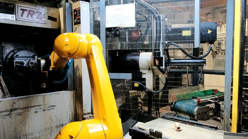
Where a transfer machine runs one part for a long time, the cell is fed in bulk. The operator brings a bin, and the cell works through it on its own. These cells feed TRZ rotary transfer machines at Torun Metal.
Timelapse
Timelapse from above, at a TRZ rotary transfer machine at Torun Metal.
01
Bin tipper
The operator brings a metal bin of 1 to 2 tonnes with a pallet truck. The tipper empties it into the hopper. How long a bin lasts depends on the part’s size and weight and on the cycle.
02
Hopper and vibratory feeder
The hopper doses the parts out, and the vibratory feeder spreads them apart.
03
Backlit conveyor and camera
Lit from below, each part shows a sharp outline. IROVISION finds it, however it lies.
04
Robot
The robot picks the part and loads it into the machine, then turns back for the next one.
3×
The operator only brings the next bin.
The robot stands a little away from the machine door, so the door stays free for service. The cell is built for a machine that runs with coolant all day: its feeder, conveyor and camera are made to work in coolant and chips.
The cell from above
Out of the machine, the next one in
At the chuck
A mounting for each machine
Transfer machines differ: where the jaws sit, how much room there is around them, how the parts arrive. So we develop the mounting for each machine, and design special robotic cells where a standard one would not fit.
01
On the machine
KTM, KAS Group. The robot hangs above the jaws, for the shortest path and the shortest cycle.
02
Beside the machine
TRZ, Torun Metal. The robot stands next to the machine, clear of its door, and the cell is fed a bin at a time.
03
On a column at its side
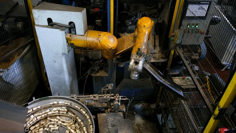
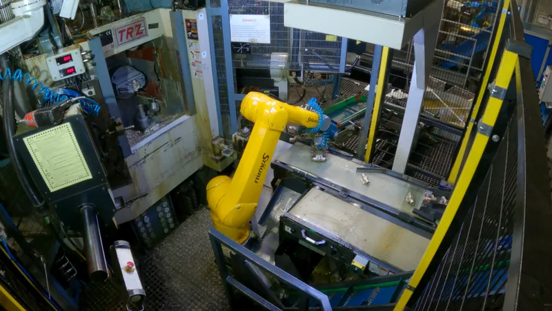
YTM. The robot is mounted on its side on a column next to the machine. It takes each part from the track of a vibratory bowl and reaches into the machine from the side.
At a YTM transfer machine: the robot on a column at the machine’s side.
Which cell fits your machine
We choose the cell with you, from your part, your machine and your cycle. Often a ROBOGUIDE simulation settles it before anything is built.
On the machine
High capacity
Parts arrive
The operator feeds the conveyor
In a bin of 1 to 2 tonnes, tipped into the hopper
Robot
Mounted above the machine
Beside the machine
Suits
Short cycles and frequent changeovers
Long runs of one part, long unattended stretches
Service
The robot goes to its saved maintenance position from the teach pendant
The robot stands clear of the machine door
Floor space
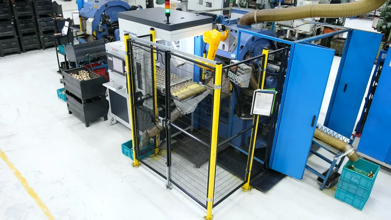
Small: the MS60L at KAS Group stands on 900 × 2,000 mm
Room for the bin tipper and the hopper
Vision
IROVISION, our own software. No part fixtures, a recipe for each part.
A first cell does not have to be the most automated one. At KAS Group the customer chose the conveyor cell on purpose: it kept the risks of a hard part under control, and the team learned robots on it. Read the story on our blog
At our plant, before the factory acceptance test. Stand-in part.
Tested at our plant first
Robot, conveyor, cameras and control cabinets sit on one base, so the whole cell is assembled, wired and run at our plant before it ships.
01
The machine, stood in for
We build pneumatic fixtures and jaws that behave like your machine, and run the full cycle against them.
02
Every function checked
Part detection, robot moves, conveyor, loading and unloading, safety functions and the cycle time.
03
Your team trained
Your operators and maintenance staff can come to the factory acceptance test and learn the cell hands-on.
04
A short start on site
The cell arrives in one piece. It is set down at the machine, connected and running soon after.
The cells at work
In production at our customers, and on test at our plant. Hover over a clip to watch it.
IROCUBE MS60L in live production at KAS GroupWatch on YouTubeIROCUBE MS60L: full-cycle test before FATWatch on YouTubeIROCUBE MS60L: final testing before FATWatch on YouTubeRobotic cell for a TRZ rotary transfer machine at Torun MetalWatch on YouTubeWhen is a robotic system ready for delivery? FAT explained (Turkish)Watch on YouTube
1 / 5
Picked under the camera
Separators keep the parts from rolling
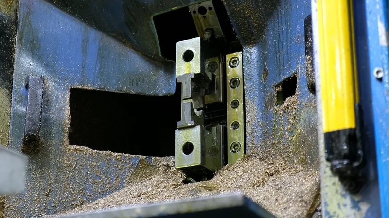
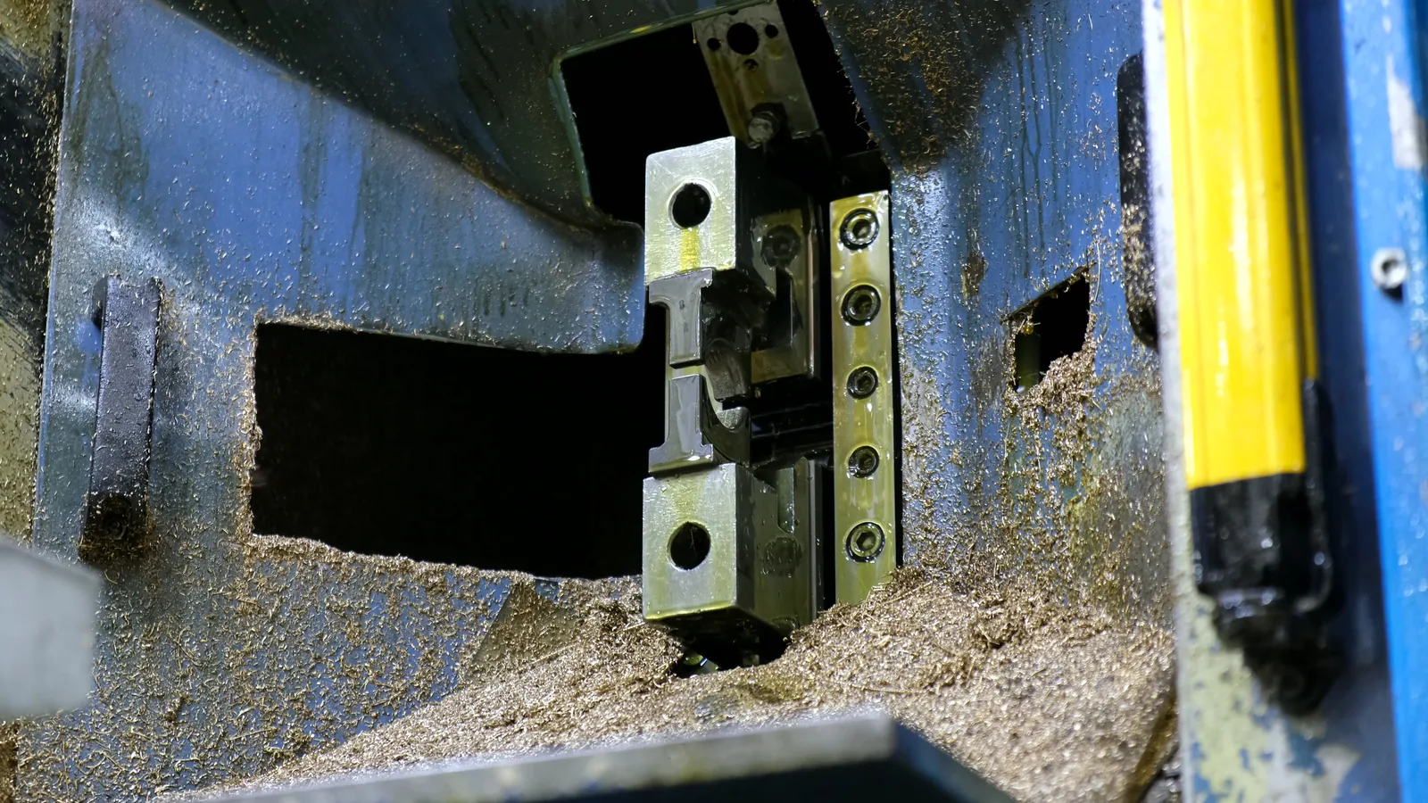
Seen from inside the machine
Pick, check, load
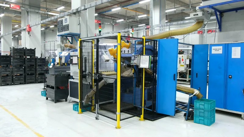
The cell at the machine
High capacity, at a TRZ machine
The MS60L in brief
Application
Feeding transfer machines
Solution
Material Handling
Reference
KAS Group, KTM transfer machine
Machines fed
KTM, TRZ and YTM transfer machines
Parts
Forged brass valve parts, 20+ types
Cycle time
4.22 s a part at KAS Group
Robot
Mounted upside down, above the machine
Vision
IROVISION, two cameras, about 83 ms an image
Conveyor
Backlit, 600 × 2,000 mm, with separators
Cell
900 × 2,000 × 2,340 mm
Safety
Guarding, and light curtains on the machine
High-capacity cell
Torun Metal, TRZ rotary transfer machines. Bin tipper for bins of 1–2 t, hopper, vibratory feeder, backlit conveyor, camera and robot beside the machine
Delivery
Built and tested at our plant on one base, trained at the factory acceptance test, commissioned at yours
We have built feeding cells for transfer machines from KTM, TRZ and YTM, rotary ones among them. Our first went into production at Torun Metal in 2014, and today our cells feed 11 transfer machines there, the TRZ rotary transfer machines on this page among them.
Send us your machine and your part, and we will tell you which cell fits.
Our forged parts still carry flash. Can you feed them?
Yes. That is often why vibratory feeding fails: the flash differs from part to part and catches in the channels. On a conveyor with separators, the camera finds each part however its flash makes it lie, and the gripper is made to cope with it. The parts at KAS Group are exactly that kind.
What happens when the machine needs service?
On the MS60L, the operator takes the teach pendant and moves the robot to its saved maintenance position, and the front of the machine is open for setup and maintenance. When the machine runs, light curtains make sure the robot is out of it before each cycle starts.
In the high-capacity cell the robot stands a little away from the machine door, so the door is always free.
How do we change over to another part?
Choose the part’s model in IROVISION and feed the new parts to the conveyor, or fill the hopper with them. If the part is new, teach it once. We train your team to do that.
How long does the cell run without an operator?
The conveyor cell runs as long as its conveyor holds parts, then the operator feeds the next batch. The high-capacity cell runs through a whole bin of 1 to 2 tonnes. How long that lasts depends on the part’s size and weight and on the cycle; we work it out with you.
What cycle time can you reach?
At KAS Group, 4.22 s a part. For your machine it depends on the part, the jaws and the distances. We confirm it with your samples, often in a simulation first.
Do you test the cell before it ships?
Yes. The whole cell is assembled and run at our plant, against fixtures and jaws that stand in for your machine. Your team can join the factory acceptance test and learn the cell there.
Send us your part and your machine
Every feeding cell starts with the part, the machine and the cycle. Tell us about them, send us samples, and we will set up the right project with you.

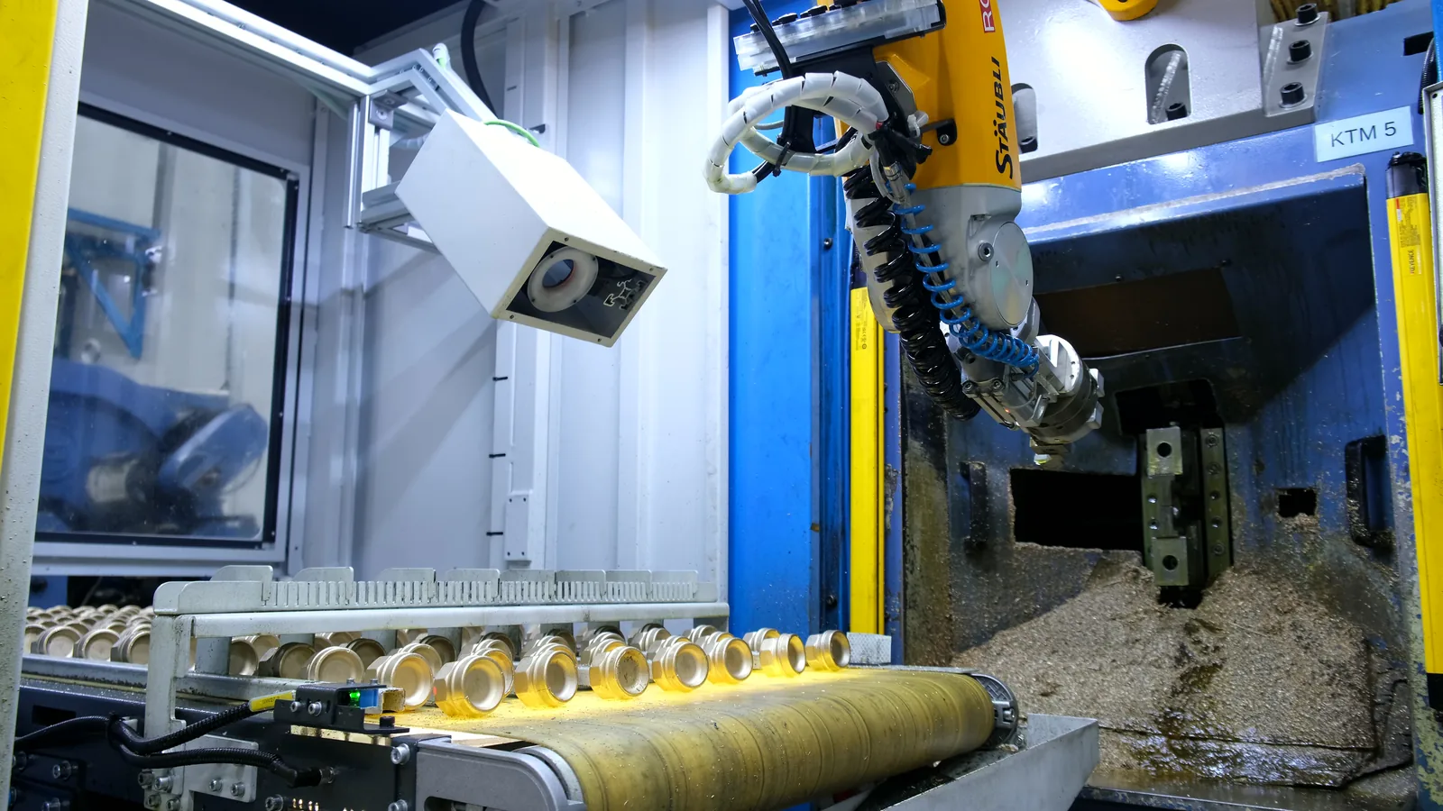
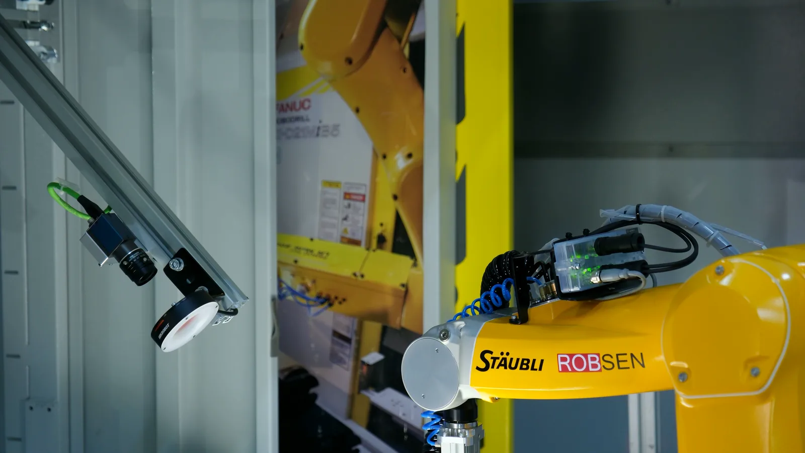
 At our plant · 2×
 At our plant