
Simulation
A cycle time from a catalogue is a guess. We build the cell in simulation first, with your part, your machine and your layout, so that the reach, the paths and the cycle are known before steel is cut, and the quote rests on them.
What the simulation settles
Five questions, answered before the quote rather than after the delivery.
- Cycle timeThe robot’s moves with your part, the machine door, the conveyor: the cycle the quote promises comes out of this model, not out of a brochure.
- Reach and layoutWhere the robot stands, or hangs, where the conveyors go, and whether the cell fits the space beside your machine.
- Collisions and safetyEvery path checked against the machine, the fixtures and the guarding; the safety zones drawn before the guarding is ordered.
- The gripperConfirmed on the part and inside the machine door before it is made. A gripper that fits the part but not the door is a common mistake, and a cheap one to catch here.
- Capacity and returnParts per shift, unattended hours, and the return per concept, from the simulated cycle rather than an assumption.
Where it decided the cell
Three cells whose shape was settled in simulation before anything was built.
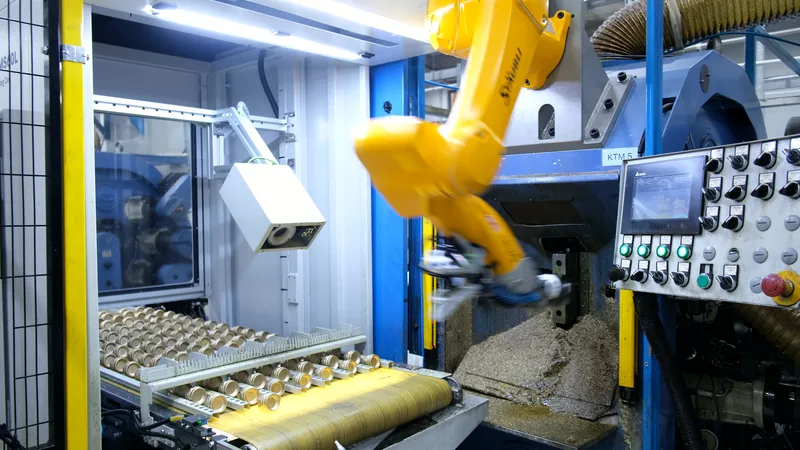
Over the machine
The cycle was too short for a robot beside the machine. The simulation put it on top, where the path to the jaws is shortest, and moved it aside for maintenance.
The cell on the machine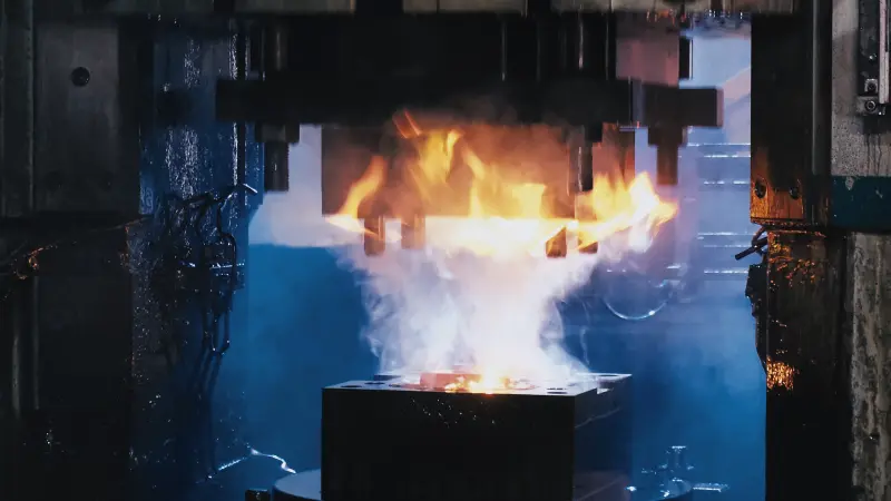
In the heat
The cycle time we quote for a forging cell comes out of the simulation with your press and your part, and a thermal analysis sets how long the tool must be.
Hot forging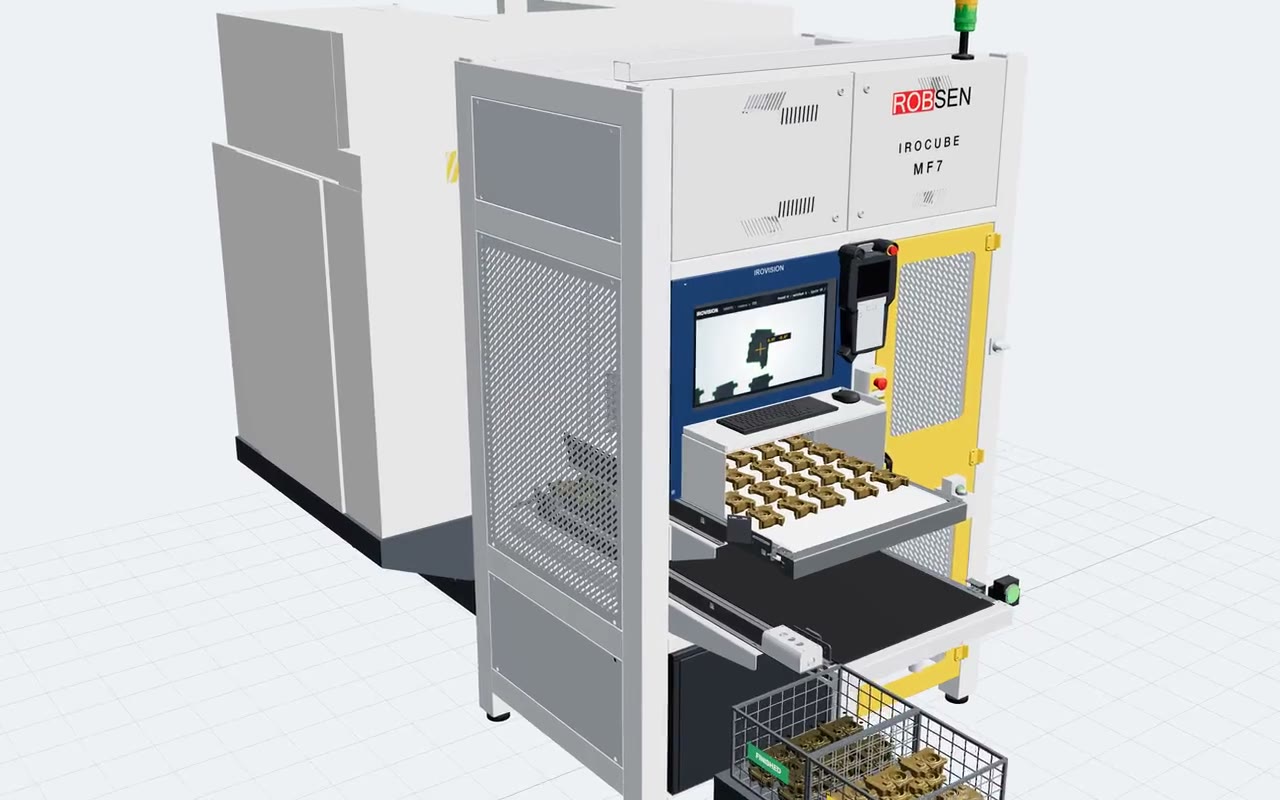
At your machine
Before we suggest an IROCUBE model, reach, cycle and layout are checked in ROBOGUIDE for your machine and your batches. One robot for two machines is decided the same way.
Machine tendingThe tools, and what they cannot do
A simulation is only as good as what goes into it. That is why it comes after the plant visit, and before the FAT.
The robot maker’s own tool
FANUC ROBOGUIDE for most of our cells, Stäubli Robotics Suite and ABB RobotStudio where those robots are used, and RoboDK. If you want to run the model yourself, a ROBOGUIDE licence is an option on IROCUBE cells.
Real inputs
Your real cycle times, the way parts arrive, the spread between one casting and the next. A model fed with nominal values gives a nominal cycle, which is why step one is a visit, not a file.
The FAT is the proof
The simulated cycle is confirmed when the cell runs with your parts at our plant. If the two disagree, we fix the cell, not the number.
- Also in Plan
- Investment Consulting · Design
- All nine
- How we work: the nine capabilities and the loop they form
Send us the layout
A drawing of the machine and the space around it, and a sample or a model of the part, is enough to start the simulation.
Talk to an engineer